A BIG IDEA.
BUILT AROUND A PERSON.
IRON-DAD is Justin’s attempt to turn a printed cosplay suit into a genuinely articulated metal costume—with support for its own weight and space for the electronics that make it fun.
The opening proposal has a bench mechanism.
A captive slide, fork, rotating leaf and sample panel now have STEP/STL files and sampled collision results. This is not yet a fitted full-suit opening system.
From a 110% print
to a clean-sheet mechanism.
The starting reference is Justin’s DaDave Mk6 cosplay suit, printed at 110% for a 6′4″ wearer. The new design does not have to duplicate that suit. The goal is an unmistakably Iron Man–inspired appearance that accommodates real movement.
Its under-armor gap plates should slide and overlap: shoulders, outer armpits, elbows, the sides of the chest, and the neck transition. Rigid plates stay out of compression folds.
The current P01 geometry is original project geometry—not an imported DaDave mesh or a finished replica. Other source models can become styling references after their licenses are checked.
- Wearer
- Justin · 6′4″ · just under 200 lb
- Measured input
- 1930.4 mm stature only
- Body proportions
- Estimated; actual measurements pending
- Entry & exit
- Independent, tool-free design objective
- Range of motion
- Compare against Justin’s normal movement
- Helmet display
- Optional future hardware
- Use
- Cosplay, making, and engineering exploration
A height-matched mannequin is not a validated fit or a body scan.
Thin shell. Useful interior.
The external surface is the styling reference. The inside is a new engineering problem.
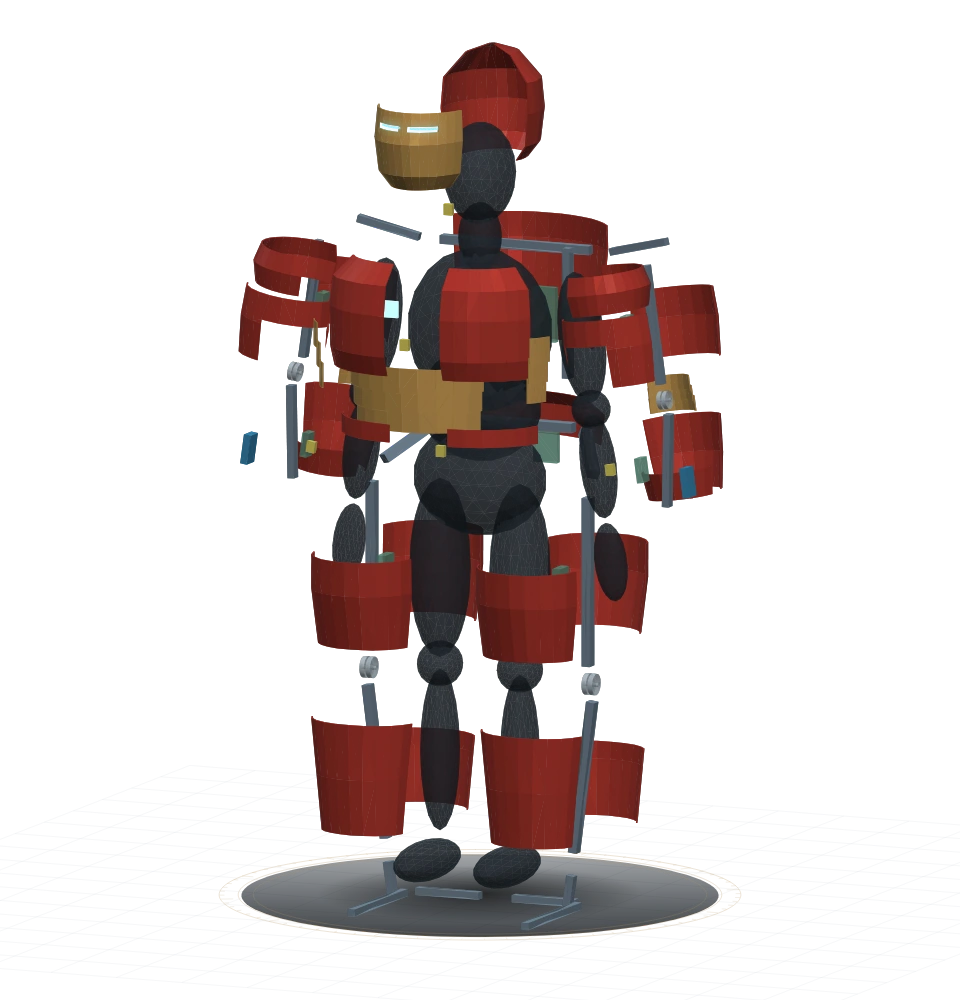 DISPLAY SEPARATION · NOT A DISASSEMBLY PATH
Cast panels—not solid costume parts.
Develop hollow-backed panels with local attachment features, finished edges, and enough interior room for movement and maintenance. Separate wearer fit scale from foundry shrinkage and machining allowances.
Removable beats permanently trapped.
Use removable skin mounts as the default. Access to wiring, padding, fasteners, and joints should not require cutting a weld. Cosmetic panels should not complete a critical structural joint.
The wall thickness is a test result.
Pattern draft, parting lines, mold filling, core strategy, alloy, casting quality, and finishing are unresolved. The STL wall thickness is not a released sand-casting specification.
3D-printed tooling is the intention. Nothing in P01 is released casting tooling. Small formed-metal lames remain an option where they make more sense than thick cast plates.
A route to the floor.
Armor mounts → arm/torso frame → pelvic structure → leg mechanisms → foot frames → ground.
Support and counterbalance are different jobs.
The design objective is for the frame to carry a measured majority of the added assembly weight while standing. Gas springs would shape joint assistance; they are not a substitute for a complete load path.
The current frame still contains unresolved shoulder, hip, ankle, and waist interfaces. Purple reference volumes in the lab show where real mechanisms are missing.
No powered limb drive in the first architecture.
Early motors are reserved for cooling and, after bench validation, light cosmetic movement. Walking, balance, and load-bearing joint actuation are not delegated to prototype software.
The first direct elbow-spring candidate reverses assistance near 126° in the recorded geometry and is rejected. No spring force or commercial part is selected.
Inspect the rejected arrangement ↗Open around the wearer.
Keep the rear structure supported. Clear overlapping panels before swinging them outward. Release the person independently of stored spring energy.
The access proposal uses captive offset/compound hinges, reachable over-center draw latches with secondary catches, and a separately opening padded harness. These are mechanism candidates, not installed hardware.
A positive-retention dressing stand would support normal solo entry. Escape away from the stand is a different requirement: independently accessible face, hand, and harness releases that do not dump the structure or require a live display.
The R02 animation sequences existing panel pivots. It does not model a finished compound hinge, fix the original opening collisions, or demonstrate self-dressing.
Explore the opening studyNIOSH · Exoskeletons in constructionFace & hands first
Keep sight, breathing access, and the hands available.
Clear, then swing
Offset the exterior panels before their outward rotation.
Support, then release
Unloaded stand-assisted dressing; a separate off-stand escape path.
Close in a reachable order
Gloves last. No hidden rear fastening needed to finish.
Padding is not leftover space.
Actual movement, breathing, and personal measurements.
Removable, adjustable interfaces and guarded edges.
Motion clearance, protected wiring, cooling, and maintenance access.
Thin cast panels and independently moving overlaps.
Conceptual zones, not a uniform concentric stack. P01’s approximate 12 mm padding screen is a geometric reservation, not a comfort specification.